the Hearth  @Felthry@awoo.space
- Pronouns
- for Fel: It/its or they/them/themself. For Rose: Zhe/zhir or she/her.
- Gender
- your guess is as good as mine
- Timezone
- UTC-8 or UTC-7 (DST)
Bot
Plural system of three, Felthry, Alaric and Rosemary. We'll sign posts with a -F, -A, or -R.
Autistic, 20-something, anxious mess
Please introduce yourself before sending a follow request.
#FelthrysVGMSelection for my music picks.
Current avatar by @hi_cial
Joined May 2017
the Hearth
boosted

re: design notes
@tsukkitsune @rey To drive the transistors? Sure, but if you've got an MCU there anyway might as well use it, unless you're GPIO-limited
-F
re: design notes
@rey here's hoping it works!
-F
@vantablack aha, we're familiar with that type of villain but didn't know it was associated with ajmes bond!
-F
what exactly are the characteristics of a "bond villain"? we've never seen a james bond movie
-F
Outernational
-F
re: design notes
@rey a final note: while you can do this with what you have already (though i would want to run the numbers on power dissipation in the 4401/4403s, they're not rated for all that much), my personal recommendation would be to use something more along the lines of the DMG2302 https://www.digikey.com/en/products/detail/diodes-incorporated/DMG2302U-7/2192636 and DMP2215 https://www.digikey.com/en/products/detail/diodes-incorporated/DMP2215L-7/1774204
both of those should have near-zero power dissipation except when switching (less than 100 mΩ of on-state resistance and no saturation voltage like bjts have) so they wouldn't even get close to warm, and you'd have nearly the full 5 V on the output
the only problem is that they're SOT-23; you may be able to make that work with some stripboard though! i've used some surface mount parts on stripboard before, though never sot-23s
-F
re: design notes
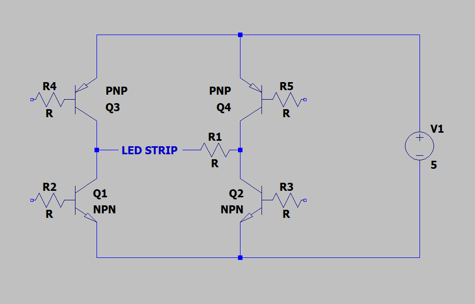
@rey that'd look something like this, by the way. You'd also have to deal with the saturation voltage of the transistors; you'd lose a bit of supply voltage on the LED strip
-F
re: design notes
@rey BJTs will work, just use npn in place of the n-channel fets and pnp for the p-channel ones. You'll have to provide the drive current for them, of course, and I think you'd have to drive them all separately so it'd take four MCU outputs instead of just two, but if that's okay then go for it!
-F
re: design notes
@rey do you have a preference on through-hole or surface-mount parts? i'd normally use SOT-23 or SOT-223 parts for this (unless it needs more current) but if you want through-hole i'll find TO-92 or TO-220 parts
-F
re: design notes
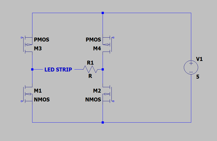
@rey Okay, then what you're going to want is something like this:
The idea is that you would turn on M2 and M3 to run power through in one direction, and turn on M1 and M4 for the other direction. It wouldn't be a bad idea to have some kind of hardware to prevent any situation where M1 and M3 or M2 and M4 are both on at the same time, as that condition shorts out the power supply
This arrangement is called an H-bridge if you want to do further research! They're usually implemented with four n-channel mosfets but i've used two n- and two p-channel ones here so that it's easier to drive it (you'd need a gate drive voltage higher than your power supply in order to turn on the upper FETs if they were n-channel)
-F
re: design notes
@rey I see! that's a pretty common arrangement for single LEDs but we've not seen it for strips before
i'll need two more bits of information then:
- Does the LED strip have built-in current limiting (if you're supposed to drive it at like 12 V or 5 V or something that's a yes) or do you need to add a resistor externally?
- What voltage and current does the LED strip run at? For max brightness, anyway; you can always run at a lower current for lower brightness
Actually if you can give us the datasheet for it that'd be even better, if you have one (a lot of stuff like this just comes from ebay or aliexpress or something with no datasheet though)
-F
re: design notes
@rey When you say "half light if V+ applied and half if V- applied" do you mean that you have two separate inputs, V+ and V-, that separately control two halves of the strip, or that applying positive voltage lights half of them and negative the other half (implying you can't light both halves at once)? Either way thi sis a simple problem and i can get a circuit for you quickly, just need to know!
-F
@rey i'd be happy to help if it's something we're vaguely familiar with
-F
i wonder if we could just ask Keysight (the modern company that is what remains of HP's test equipment department)
they might not still have it, but they also might
-F
re: Pokémon / furry nsfw stupid
@bucktoy heck those are good balls though
-F
actually, would anyone happen to be good at digging up old manuals? i feel like this one would be a fascinating one to go through but our attempts have so far been stymied by the fact that modern HP has reused the number for a printer
-F
that flyback transformer is the source of the ticking i mentioned earlier, by the way. under no load it operates at about 1~4 Hz depending on the set voltage, making a tick every time it switches, and as the load increases it ticks more, up to a maximum of something around 3~4 kHz (by our ear, anyway--we don't have perfect pitch so this is a very rough estimate)
it's quite something to look inside
-F
maybe we'll try to reverse engineer it sometime
it's not that complicated a thing; the dials on the front are just decade switches for resistances (and the 1s digit is a potentiometer for fine adjustment), that'll obviously just be a divider in the feedback network (probably a kelvin-varley divider?)
the converter itself is an enormous flyback--i do mean enormous, the flyback transformer is about the size of a box of tissues--running in a variable frequency mode
-F
it's a high voltage power supply, 4 kV/50 mA (max of 2 kV from ground, but the output is floating so you can do ±2 kV for a total of 4), and it's from an era where they advertised it being fully solid-state as a big selling point
and honestly that is a big selling point now, too; getting old equipment that uses tubes is always a pain because sometimes the tubes need replacing and sometimes they're ones that you can't get anymore
would love to have the schematics for it
-F
- Pronouns
- for Fel: It/its or they/them/themself. For Rose: Zhe/zhir or she/her.
- Gender
- your guess is as good as mine
- Timezone
- UTC-8 or UTC-7 (DST)
Bot
Plural system of three, Felthry, Alaric and Rosemary. We'll sign posts with a -F, -A, or -R.
Autistic, 20-something, anxious mess
Please introduce yourself before sending a follow request.
#FelthrysVGMSelection for my music picks.
Current avatar by @hi_cial
Joined May 2017